Next step is going to be to find a way to render stuff on our matrix!
Data structures
Register output: io-bits
(For RPi Model B Rev2)
 1union io_bits {
 2  struct {
 3    bits_t unused : 2;              // 0-1
 4    bits_t output_enable_rev2 : 1;  // 2
 5    bits_t clock_rev2  : 1;         // 3
 6    bits_t strobe : 1;              // 4
 7    bits_t unused2 : 2;             // 5..6
 8    bits_t row : 4;                 // 7..10
 9    bits_t unused3 : 6;             // 11..16
10    bits_t r1 : 1;                  // 17
11    bits_t g1 : 1;                  // 18
12    bits_t unused4 : 3;
13    bits_t b1 : 1;                  // 22
14    bits_t r2 : 1;                  // 23
15    bits_t g2 : 1;                  // 24
16    bits_t b2 : 1;                  // 25
17    } bits;
18
19    uint32_t raw;
20};
The size of this struct is 26 → less than 32 so we can use a 32-bit integer to define our register output.
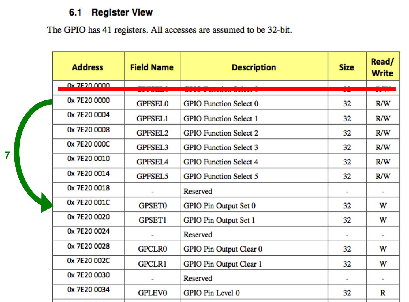
The register we’re going to write the struct into is the has the address 0x001C. (Note: You first need to write to the 0x0028 register to clear the GPIO pins first)
Bit-planes
The data is going to be organized a bit-plane of io_bits. The bit-plane contains colums times double-row io_bit structs. (Double-rows is the amount of rows divided by 2.)
This is because if you have a matrix with 32 rows for example you are going to have to address the rows by 4 bits. \(2^4\) is 16, which is \(32 / 2\). For a 16 pixels high matrix you have a 3 bit address: \(16 / 2 = 2^3\). A 32 pixels high matrix is basically a matrix of two 16x32 forged together. If we want to control the upper part we need to set R1,G1,B1. For the lower part: R2,G2,B2. That’s why we only need half the space for our bit-plane. The io_bits struct just contains more information than obvious.
On the raspberry’s hardware we’re going to use 11 bit-planes. More details later.
Filling our bit-planes
We’re going to iterate over all bit-planes we want to fill. Then we’re going to check if we want to turn the R, G or B output on. Now just set the output’s we need and copy the data to each double-row and column.
 1
 2const uint16_t red = map_color(matrix, rgb->r);
 3const uint16_t green = map_color(matrix, rgb->g);
 4const uint16_t blue = map_color(matrix, rgb->b);
 5
 6//Iterate over bit-planes
 7for (i = MAX_BITPLANES - matrix->pwm_bits; i < MAX_BITPLANES; ++i) {
 8  // The bit we check in our color
 9  int mask = 1 << i;
10
11  int r = (red & mask) == mask; // Check if i-th bit in red is set
12  int b = (blue & mask) == mask; // Check if i-th bit in blue is set
13  int g = (green & mask) == mask; // Check if i-th bit in green is set
14
15  io_bits plane_bits = { 0 };
16  plane_bits.bits.r1 = plane_bits.bits.r2 = (bits_t) r;
17  plane_bits.bits.g1 = plane_bits.bits.g2 = (bits_t) g;
18  plane_bits.bits.b1 = plane_bits.bits.b2 = (bits_t) b;
19
20  for (row = 0; row < double_rows; ++row) { // Iterate over all double-rows
21    io_bits *row_data = lm_io_bits_value_at(bitplane, columns, row, 0, i);
22    for (col = 0; col < columns; ++col) { // Iterate over all columns
23      (row_data++)->raw = plane_bits.raw; // Copy data
24    }
25  }
26}
We’re creating matrix->pwm_bits io_bits. Because the more io_bits we use the more we’re going to PWM our LEDs. More data → greater color-depth.More on this later.
Throw this data at our matrix!
First prepare some masks we’re going to need later on.
 1io_bits color_clock_mask = { 0 };   // Mask of bits we need to set while clocking in.
 2io_bits clock = { 0 }, output_enable = { 0 }, strobe = { 0 }, row_address = { 0 };
 3io_bits row_mask = { 0 };
 4
 5// Color & clock
 6color_clock_mask.bits.r1 = color_clock_mask.bits.g1 = color_clock_mask.bits.b1 = 1;
 7color_clock_mask.bits.r2 = color_clock_mask.bits.g2 = color_clock_mask.bits.b2 = 1;
 8SET_CLOCK(color_clock_mask.bits, 1);
 9
10// Row mask
11row_mask.bits.row = 0x0f;
12
13// Clock
14SET_CLOCK(clock.bits, 1);
15
16// EO
17ENABLE_OUTPUT(output_enable.bits, 1);
18
19// Strobe
20strobe.bits.strobe = 1;
We start by iterating over all double-rows.
1for (d_row = 0; d_row < double_rows; ++d_row) {
Now we’re setting our current row address which basically is our iteration value d_row. (Apply bit mask as we really only want to send the address which is max 0xF)
1  row_address.bits.row = d_row;
2  lm_gpio_set_masked_bits(row_address.raw, row_mask.raw);  // Set row address
Start PWM-ing our LEDs! We start at COLOR_SHIFT, which is MAX_BITPLANES - CHAR_BIT, since the first 3 PWM loops are basically useless as the raspberry can’t time that precisely. Still the wither pm_bits, the more often we need to iterate.
1 for (b = COLOR_SHIFT + MAX_BITPLANES - pwm_bits; b < MAX_BITPLANES; ++b) {
Get the row data for our current d_row for column 0, iterate over all columns, write R1,G1,B1 and R2,G2,B2 and clock the color in.
1    io_bits *row_data = lm_io_bits_value_at(bitplane, columns, d_row, 0, b);
2
3    for (col = 0; col < columns; ++col) {
4      const io_bits out = *row_data++;
5      lm_gpio_set_masked_bits(out.raw, color_clock_mask.raw);
6      lm_gpio_set_bits(clock.raw);
7    }
Clock back to normal.
1 lm_gpio_clear_bits(color_clock_mask.raw);
Strobe in current row.
1    lm_gpio_set_bits(strobe.raw);
2    lm_gpio_clear_bits(strobe.raw);
The last step is to sleep for a specific amount of time.
1 sleep_nanos(sleep_timings[b]);
One loop is finished now, repeat this now as fast as possible
1  }
2}
Raspberry: “How long do I need to wait?”
The code to generate the timings is as follows:
1long base_time_nanos = 200;
2long row_sleep_timings[MAX_BITPLANES];
3
4for (i = 0; i < MAX_BITPLANES; ++i) {
5  row_sleep_timings[i] = (1 << i) * base_time_nanos;
6}
which will output (Credits go to https://github.com/hzeller/rpi-rgb-led-matrix):
 1row_sleep_timings[0]: (1 * base_time_nanos)
 2row_sleep_timings[1]: (2 * base_time_nanos)
 3row_sleep_timings[2]: (4 * base_time_nanos)
 4row_sleep_timings[3]: (8 * base_time_nanos)
 5row_sleep_timings[4]: (16 * base_time_nanos)
 6row_sleep_timings[5]: (32 * base_time_nanos)
 7row_sleep_timings[6]: (64 * base_time_nanos)
 8row_sleep_timings[7]: (128 * base_time_nanos)
 9row_sleep_timings[8]: (256 * base_time_nanos)
10row_sleep_timings[9]: (512 * base_time_nanos)
11row_sleep_timings[10]: (1024 * base_time_nanos)
Accessing individual pixels
 1uint16_t x, uint16_t y;
 2
 3io_bits *bits = lm_io_bits_value_at(matrix->hot_bitplane_buffer, matrix->columns, y & matrix->row_mask, x, min_bit_plane);
 4if (y < double_rows) { // Top
 5  for (i = min_bit_plane; i < MAX_BITPLANES; ++i) {
 6    int mask = 1 << i;
 7
 8    bits->bits.r1 = (bits_t) ((red & mask) == mask);
 9    bits->bits.g1 = (bits_t) ((green & mask) == mask);
10    bits->bits.b1 = (bits_t) ((blue & mask) == mask);
11    bits += columns;
12  }
13} else { // Bottom
14  for (i = min_bit_plane; i < MAX_BITPLANES; ++i) {
15    int mask = 1 << i;
16    bits->bits.r2 = (bits_t) ((red & mask) == mask);
17    bits->bits.g2 = (bits_t) ((green & mask) == mask);
18    bits->bits.b2 = (bits_t) ((blue & mask) == mask);
19    bits += columns;
20  }
21}
Basically we’re doing the same, except that we bitwise AND y and double_rows - 1. So 16 and 32 becomes 0, 6 and 16+6 becomes 6. Furthermore we’re modifying only the io_bits with correspond to our x value.