I got myself a Dreame vacuum robot with the goal of – cleaning. Yes, I did not have the goal originally to root my vacuum. However, in case I ever want to sideload software onto the robot, I picked one that is reliably rootable. The Dreame X40 looked decent, and Dennis Giese did awesome work on getting root access to it back in 2021. This turned out to be a good decision as at some point I was starting to become a bit freaked out by the robot’s camera and decided to checkout the security of the robot.
Even though the process is clearly written up in a PDF, I had some open questions:
- How does the rooting method work? Which security measures are circumvented?
- The PDF mentioned that calibration data and device ID are lost. Why is that? Can I do a backup before rooting?
- Can I do a full flash backup so reverting is possible?
- What are the
dustx100.binfiles? Are those the flash dumps I’m looking for? - The Fastboot mode looks a bit odd. How is it related to Fastboot on Android?
- Where do the binaries used during rooting come from? Who created them?
This blog post is answering these questions.
My main motivation here is to learn about how the Dreame X40 works and prepare for some deeper security audit.
I want to avoid losing any data/features when rooting it. The first step is to gain root access. After that, topics like cloud connectivity, the MCU, etc. can be vetted. If, for instance, the device ID is lost, I would have little hope of analyzing the connectivity deeper.
FEL rooting method overview
Ideally, first read the PDF as it goes into full detail. In summary the rooting method follows these steps:
- Make your laptop listen for FEL devices and connect the robot via USB.
- Boot the Dreame robot into FEL mode by grounding
BOOT_SELwhile booting the robot. - Write a U-Boot image to memory and start it. In the PDF this is done using Phoenixsuit on Windows and LiveSuit on Debian (⚠️ Download at your own risk. These are random binaries off the Internet!)
- The U-Boot image launches into Fastboot mode. U-Boot is using the fastboot protocol, but this does not mean that all commands are available, or the OEM implemented custom ones.
- Now we flash the
toc1,boot1,boot2,rootfs1androotfs2partitions. The update totoc1disables secure boot. However, I have not verified how it does that.
The linked FEL images in the PDF contain a U-Boot version with custom fastboot commands. Here is an overview of the functionality.
| Command | Description |
|---|---|
fastboot getvar config |
You have to call this before other commands. Prints a MD5 hash for identification. |
fastboot getvar product |
Returns “Android Fastboot” |
fastboot getvar dustversion |
A hardcoded string returning the version of the FEL image. |
fastboot getvar ramsize |
The size of the ram. |
fastboot getvar flashsize |
The size of the flash. |
fastboot getvar toc0hash |
MD5 hash of the toc0 partition. |
fastboot getvar toc1hash |
MD5 hash of the toc1 partition. |
fastboot getvar toc1version |
Unknown. |
fastboot getvar minicg |
Unknown. |
fastboot get_staged dust.bin |
Downloads flash data to the file dust.bin. This data is encrypted (more on this later). |
fastboot oem prep |
Not sure yet what this does. |
fastboot flash <part> <file> |
Flashes a partition (e.g., rootfs, boot) with the specified image file. |
Dumping the flash
To preserve as much data from the “non-rooted” state, I was really after a flash dump. I wondered if the rooting method gives me some hints on how I could dump the flash. The FEL mode is the debugging feature used in the above rooting method. According to this blog post, FEL allows you to write to memory and execute it. Actually, the blog post gives some insights on what is likely happening when using LiveSuit/Phoenixsuit. It just “boot” from an in-memory u-boot image.
FEL does not give access to the flash, but it allows you to execute arbitrary code with quite a high privilege. Binaries executed in their context have access to the flash, which is what I’m looking for.
Now, the dumps you can crab using get_staged caught my attention. They are in total ~1200MB which seemed too large for a memory dump. Also, which memory would you copy? Likely, the memory would not contain any meaningful data just after boot.
So the suspicion is that those are actual flash dumps. Executing binwalk on them contradicts this idea, though. Their entropy is high throughout the file.
binwalk -e.This suggests the dumps are encrypted. This struck me as pretty weird. Why would they be encrypted? Unfortunately, I did not yet find out. Let’s continue, as it turns out it’s pretty easy to decrypt them.
Unpacking a FEL image
I reproduced entering fastboot on Windows as well. This was mostly to sanity check my understanding in the beginning when I barely understood anything about FEL yet.
The tool imgRePacker is capable of unpacking FEL images, like the one you can download from builder.dontvacuum.me/nextgen. There are also similar images provided in the downloads from builder.dontvacuum.me/_dreame_r2416, but I have not yet diffed them.
The unpacked image looks like this:
 1[4.0K]  dust-livesuit-mr813-ddr4.img.dump
 2├── [   6]  arisc.fex
 3├── [149K]  aultls32.fex
 4├── [163K]  aultools.fex
 5├── [1.0K]  board.fex
 6├── [1.7K]  cardscript.fex
 7├── [ 72K]  cardtool.fex
 8├── [ 19K]  config.fex
 9├── [ 16K]  dlinfo.fex
10├── [128K]  env.fex
11├── [ 44K]  fes1.fex
12├── [2.3K]  image.cfg
13├── [4.0K]  _iso
14├── [ 512]  split_xxxx.fex
15├── [109K]  sunxi.fex
16├── [8.0K]  sunxi_gpt.fex
17├── [ 12K]  sys_config.fex
18├── [ 165]  sys_partition.fex
19├── [ 98K]  toc0.fex
20├── [ 99K]  toc0.fex.png
21├── [1.1M]  toc1.fex
22├── [226K]  toc1.fex.png
23├── [245K]  u-boot.fex
24├── [113K]  u-boot.fex.png
25├── [180K]  usbtool.fex
26├── [   4]  Venv.fex
27└── [   8]  vmlinux.fex
The most interesting code is likely in one of the larger binaries. So that would be either toc0.fex, toc1.fex or u-boot.fex. As we saw some custom Fastboot commands that are implemented in U-Boot I first took a look at that.
Reversing U-Boot
I started by loading u-boot.fex into Ghidra.
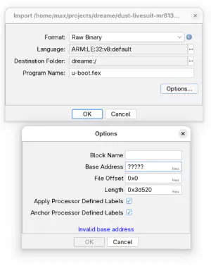
0x4a000000 here.Initially, I left the base address at 0 and then quickly figured out that the base address is 0x4a000000. This is the address where u-boot expects to be loaded into memory.
From there, I looked for strings containing “dust” and quickly found the Fastboot handling code.
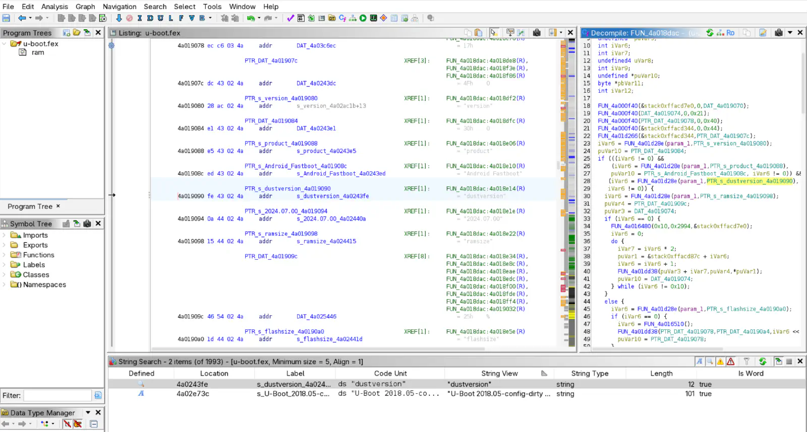
From there, I started reverse engineering the first Fastboot commands like getvar. I also found some weird Fastboot OEM commands that I did not yet investigate, like bko, upload, bypass, debug or a command starting with fan and ending in pi.
Within the getvar function, I found that you can return the flash size.
Now, likely the same code calculating the size of the flash is also used to dump it.
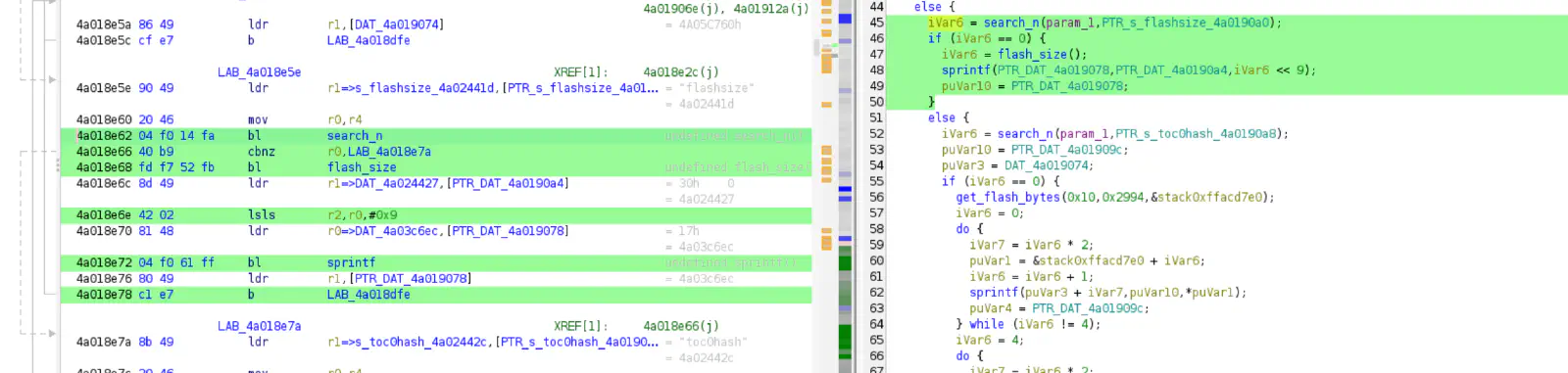
Bingo! There is only one reference to the function flash_size.
Note: When reversing its often really nice to have some reference function like the
sprintffunction above. So investing time into identifying the generic and simple ones is well spent time. I also used these U-Boot sources and diffed the code with the decompiled one to identify functions.
At 0x4a01918c we find the function upload that gets data from the flash and puts it into a buffer, which will be transmitted over USB using the Fastboot protocol.
Interesting observations are that it copies 0x40000 bytes, which match the file size of the dump files. CURRENT_STAGE is either 0/1/2. It is controlled by the Fastboot commands oem reset, oem stage1 and oem stage2. Based on this value, either flash memory from the beginning or a certain offset is taken. The stage() function takes a buffer and sends it over USB.
Note that this upload function uses the Fastboot protocol. This is why it is starting by sending a string like “DATA: %08x” as defined in the Fastboot documentation:
DATA -> the requested command is ready for the data phase. A DATA response packet will be 12 bytes long, in the form of DATA00000000 where the 8 digit hexidecimal number represents the total data size to transfer.
We can also see some light XOR encryption here within the most inner do-while loop.
The encryption key is taken from xorTableAddress. The data for the key is at 0x4a03c760. Initially, I thought the key would be just in the binary. However, the key is 0x200 * 0xFF bytes long.
This is because each chunk is 0x200 bytes long, and we take the last byte from the blockIndex to address the byte in the key.
We would reach end-of-file before being able to read the whole key from the binary alone.
Before we dive into how the encryption key is generated, here is the decompiled code for the upload function I ended up with:
 1
 2void upload(void)
 3
 4{
 5  uint currentFlashBatchsize;
 6  undefined4 len;
 7  int byteIndex;
 8  uint uploadBlockStart;
 9  uint uploadBlockEnd;
10  uint blockSize;
11  uint blockIndex;
12  uint 0x40000-1;
13  int xorTableAddress;
14
15  0x40000-1 = value3FFFFF;
16  currentFlashBatchsize = flash_size();
17  hash_init(&stack0xf7fffd88);
18  xorTableAddress = xortable;
19  hash_md5(&stack0xf7fffd88,currentFlashBatchsize,4);
20  MD5Final(DAT_4a019270,&stack0xf7fffd88);
21  if (DAT_4a019274 < currentFlashBatchsize << 9) {
22    currentFlashBatchsize = value7800;
23  }
24  sprintf(&stack0xf7fffd44,str_DATA%x,currentFlashBatchsize << 9);
25  len = str_len(&stack0xf7fffd44);
26  stage(&stack0xf7fffd44,len);
27  uploadBlockStart = currentFlashBatchsize * *CURRENT_STAGE;
28  uploadBlockEnd = uploadBlockStart + currentFlashBatchsize;
29  for (; uploadBlockStart < uploadBlockEnd; uploadBlockStart = uploadBlockStart + 0x40000) {
30    blockSize = currentFlashBatchsize;
31    if (0x40000-1 < currentFlashBatchsize) {
32      blockSize = 0x40000;
33    }
34    blockIndex = 0;
35    get_flash_bytes(uploadBlockStart,0x40000,&stack0xf7ffffe0);
36    do {
37      memcpy(&stack0xf7fffde0,&stack0xf7ffffe0 + blockIndex * 0x200,0x200);
38      byteIndex = 0;
39      do {
40        (&stack0xf7fffde0)[byteIndex] =
41             *(byte *)(xorTableAddress + (blockIndex & 0xff) * 0x200 + byteIndex) ^
42             (&stack0xf7fffde0)[byteIndex];
43        byteIndex = byteIndex + 1;
44      } while (byteIndex != 0x200);
45      blockIndex = blockIndex + 1;
46      stage();
47    } while (blockSize != blockIndex);
48    currentFlashBatchsize = currentFlashBatchsize - 0x40000;
49  }
50  str_fn1(&stack0xf7fffd44,OKAY);
51  len = str_len(&stack0xf7fffd44);
52  stage(&stack0xf7fffd44,len);
53  return;
54}
This means the key is calculated dynamically during runtime. Following the references from the XOR table, we reach a function at 0x4a01956c which I called generate_xor_table. This function is probably invoked statically during initialization.
This function generates the key by starting from the seed 0xc9acbcc6 and iteratively generating the key.
Here is the partially decompiled code I ended up with:
 1int generate_xor_table(void)
 2
 3{
 4  int iVar1;
 5  undefined4 *puVar2;
 6  int index;
 7  undefined1 ctx [88];
 8  undefined1 ctx1 [92];
 9  int table;
10
11  table = ptr_xortable;
12  index = 0;
13  hash_init(ctx);
14  hash_md5(ctx,table_start_Hash_c9_AC_BC_C6,4);
15  MD5Final(ptr_xortable,ctx);
16  do {
17    hash_init(ctx1);
18    hash_md5(ctx1,ptr_xortable,0x20000);
19    iVar1 = index * 0x10;
20    index = index + 1;
21    MD5Final(table + iVar1,ctx1);
22    puVar2 = DAT_4a01960c;
23  } while (index != 0x2000);
24  memset(DAT_4a01960c,0,0x1c);
25  *DAT_4a019610 = 0;
26  *(undefined4 *)PTR_DAT_4a019614 = 0;
27  *(undefined4 *)PTR_DAT_4a019618 = 0;
28  *puVar2 = 0x41000000;
29  table = maybe_malloc(0x10000);
30  puVar2[4] = table;
31  if (table == 0) {
32    maybe_free(*puVar2);
33    table = -1;
34  }
35  else {
36    table = env_get(ptr_str_serial_number);
37    if (table != 0) {
38      maybe_str_cpy(*(undefined4 *)(ptr_maybe_Android_Fastboot + 8),table,0x18);
39      table = 0;
40    }
41  }
42  return table;
43}
It’s 2025, and we got LLMs, so it would be a waste of time to translate this code to, e.g., Python. The resulting key is independent of any serial number, so the key should work for any flash dumps.
Summary of Reversing U-Boot
By reversing the U-Boot I was able to find some non-public functionality.
The generate_xor_table can be used to generate an XOR key. By inverting the upload function, flash dumps can be decrypted now.
Open Questions
We were able to answer some of the questions we started with:
- How does the rooting method work? Which security measures are circumvented?
The rooting works by disabling secure boot by first overwriting the toc1 partition and then the rootfs partition. It’s unclear yet how toc1 is patched to disable secure boot.
- The PDF mentioned that calibration data and device ID are lost. Why is that? Can I do a backup before rooting?
I did not see any hints of calibration data getting lost. Calibration data looks similar before and after the root (/data/misc/caliberation_result.json). I did not yet investigate device ID. But I believe did is equal to device ID (/mnt/private/ULI/factory/did.txt).
- Can I do a full flash backup so reverting is possible?
Yes you can do that. I’m pretty sure reverting should work without any issues if you grabbed the dustx100.bin files. I showed how to decrypt the files in this blog post.
- What are the
dustx100.binfiles? Are those the flash dumps I’m looking for?
They are encrypted flash dumps of the first ~1200MB of flash storage.
- The Fastboot mode looks a bit odd. How is it related to Fastboot on Android?
Fastboot was introduced with Android. However, the implementation used here is not related to Android.
- Where do the binaries used during rooting come from? Who created them?
I don’t know yet how to reproduce the FEL images used for rooting.
There is some functionality I do not yet understand (e.g. oem dunst and oem prep), but likely it’s also not relevant for my goal, which is observing what the Dreame robot is doing during normal operation to discover security flaws.
Also, I’m very unsure why the flash dumps are encrypted. This creates a dependence on the author of the rooting method. If you brick your device, you need help from them. If you would just have the flash dump, then I would assume reverting your robot should “just work”.
I also wondered why the flash dump is only 1200MB while the whole flash is 4GB of the Dreame X40. The most important partitions are in the first 500MB as this partition layout shows:
 1GPT fdisk (gdisk) version 1.0.10
 2
 3Partition table scan:
 4  MBR: protective
 5  BSD: not present
 6  APM: not present
 7  GPT: present
 8
 9Found valid GPT with protective MBR; using GPT.
10
11Command (? for help): p
12Disk mmcblk0.img: 7634944 sectors, 3.6 GiB
13Sector size (logical): 512 bytes
14Disk identifier (GUID): AB6F3888-569A-4926-9668-80941DCB40BC
15Partition table holds up to 12 entries
16Main partition table begins at sector 2 and ends at sector 4
17First usable sector is 41984, last usable sector is 7634910
18Partitions will be aligned on 512-sector boundaries
19Total free space is 0 sectors (0 bytes)
20
21Number  Start (sector)    End (sector)  Size       Code  Name
22   1           41984           42495   256.0 KiB   0700  boot-resource
23   2           42496           43519   512.0 KiB   0700  env
24   3           43520           44543   512.0 KiB   0700  env-redund
25   4           44544          105983   30.0 MiB    0700  boot1
26   5          105984          515583   200.0 MiB   0700  rootfs1
27   6          515584          577023   30.0 MiB    0700  boot2
28   7          577024          986623   200.0 MiB   0700  rootfs2
29   8          986624          987647   512.0 KiB   0700  private
30   9          987648          995839   4.0 MiB     0700  misc
31  10          995840          996863   512.0 KiB   0700  record
32  11          996864          997887   512.0 KiB   0700  pstore
33  12          997888         7634910   3.2 GiB     0700  UDISK
I believe the choice of 1200MB is to limit the amount of pictures that might be included in the flash dump. However, in my dump, I could find hundreds of pictures of my flat. The robot likely deleted them, but did not yet overwrite them. Therefore, hackers who want to root their Dreame’s should store their dustx100.bin, dustx101.bin and dustx102.bin files in a safe and also secure place.
To summarize:
- What does
oem dunstandoem prepdo? - What is the device ID
did? - Can we authrorize to the Dreame API using the data we got from the robot?
- Which binaries run on the robot? What does the MCU do?
- There seem to be different FEL images available. One intended to do dumping of the flash and then one for the rooting/secure boot disabling.
- There are some more hidden Fastboot commands that might be interesting to see what they do.
I’m super happy now that I can continue working on this robot and analyzing the kernel and user space.
Links
- Open-source FEL tool: https://linux-sunxi.org/Sunxi-tools
- Information about FEL images: https://linux-sunxi.org/LiveSuit_images